

Impedance Relays in Distance Protection Strategies
Welcome to a realm where advanced technology meets the critical task of safeguarding our most vital power transmission lines. Ensuring uninterrupted electricity flow is paramount in energy distribution, especially across high-voltage and extra-high-voltage transmission lines. Enter the world of “Impedance Relays in Distance Protection Strategies,” a domain where the marriage of cutting-edge relay technology and the science of electrical impedance forms an unyielding shield against potential disruptions. As we delve into this article, we unravel the mechanisms that make impedance relays a cornerstone of distance protection, elevating the standards of grid reliability and resilience. Join us as we explore how these ingenious devices transform the landscape of power transmission safety, ushering in an era of enhanced protection and unparalleled efficiency.
Distance Protection Strategies are essential for enhancing the security and reliability of the power grid. Specifically, they rely on distance relays and precise impedance measurements to detect and isolate faults. Moreover, with increasing fault current and power swings, advanced relay settings, automation, and monitoring are necessary to improve system response.
In addition, engineers must consider factors like integration, overcurrent protection, and regular maintenance. Tools such as simulation software and real-world case studies and events support more accurate decisions. Furthermore, sharing information through articles, forums, and LinkedIn helps address key challenges and strengthens protection systems across substations and distribution systems.
Impedance Relays for Transmission Line Protection
Types of Distance Protection Relay
The distance protection relay family consists of the following types of Relays:
- Impedance Relays
- Reactance Relays
- MHO Relays or Admittance Relays.
Join us on a journey to explore the realm of the Impedance Relay, unraveling its inner workings and discovering how it contributes to the safe and reliable operation of power systems.
Impedance Relay
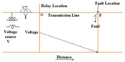
Construction of Impedance Relay
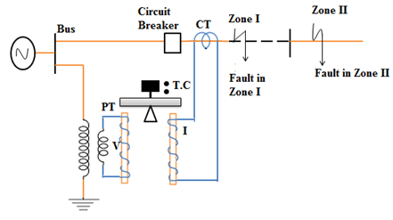
Operating Principle of Impedance Relay
Fig shows a simple form of EM balanced beam impedance relay. It has a fixed beam and two electromagnets (EM). The zone’s voltage energizes one EM through PT, and the zone’s current energizes the other EM through CT.
Under no-fault conditions, the pull due to the voltage element will be more than the pull due to the current part, and the trip circuit (TC) will remain open.
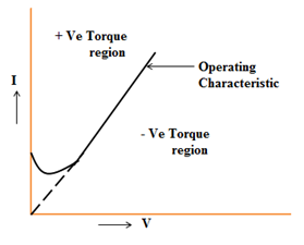
The operating characteristics of the circuit’s impedance are compared with the voltage at the relay location. The current produces a positive torque, called an Operating Torque, and the voltage has a negative torque, called a Restraining Torque.
This equation for the operating torque of an electromagnetic relay is:
T = K1 I2 – K2V2 – K3
K1, K2, and K3 are constants, K3 being the torque due to the control spring effect.
Neglecting the effect of the spring used, which is very small, the torque equation can be written as:
T = K1 I2 – K2V2
For the operation of the relay, the following conditions should be satisfied.
V2/I2 < K1/K2
V/I < K where K is a constant.
as V/I is Z, Z<K.
The above expression explains that the relay is on the verge of operation when the ratio of V to I, i.e., the measured value of line impedance, is equal to a given constant. The relay operates if the measured Z is less than the given constant. This given constant is a design value depending on the total length of the HT / EHT feeder to be protected.
Operating Characteristics of an Impedance Relay
R-X Diagram
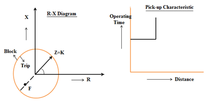
Directional Impedance Relay
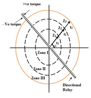
Three impedance relays and a directional unit connected in series with the impedance relays are provided at any relay location.
Zone-I’s impedance is Z1. If a fault occurs at F1, the impedance of zone-I reduces to a lower value than the pre-set value (Z1). Due to this, the circuit increases and operates the relay.
For any fault at zone-II F2 in the figure, the impedance of zone-I will not change, and the relay will not operate.
Zones of Protection by Impedance Relay

The second unit protects the rest, 20% of the protected line and 50% of the shortest adjoining line. This zone of protection is called the second zone of protection. The dual zone unit operates after a certain time delay. Its operating time is 0.2 to 0.5 sec.
The third unit is a backup of the adjoining line. Its setting covers the first line, i.e., the protected line, plus the longest second line, plus 25% of the third line. The time of relay operation is 0.4 to 1 sec.
Because of the cost involved and relay panel space restrictions, only one measuring unit is employed for all three protection zones nowadays. The timing unit sets the distance settings for II and III zones. The figure represents the stepped time–distance characteristics of impedance relays.
Conclusion
Impedance relays play a critical role in protecting and reliability of power systems. By accurately measuring impedance to detect faults, these relays ensure quick and selective isolation of faulty sections, preventing damage and maintaining system stability. Various impedance relays, including simple impedance relays, directional impedance relays, mho relays, and quadrilateral relays, offer tailored solutions for different protection needs.
The applications of impedance relays in transmission lines, generators, and transformers highlight their versatility and importance in maintaining the integrity of power systems. Despite the complexity involved in setting and calibrating these relays, their advantages in sensitivity, directional capability, and adaptability make them indispensable tools for power system protection.
FAQs
What is an impedance relay, and how does it function?
An impedance relay is a protective relay used in power systems to detect faults. It measures the impedance (resistance and reactance) between the relay location and the fault. When a fault occurs, the impedance changes, and if it falls within a predefined range, the relay activates to isolate the faulty section, protecting the system from damage.
What are the different types of impedance relays?
There are several types of impedance relays, including:
- Simple Impedance Relay: Operates when the measured impedance falls below a set value. It is straightforward but may lack selectivity.
- Directional Impedance Relay: This relay adds a directional element to ensure it operates only for faults in a specific direction, improving selectivity and reducing false trips.
- Mho Relay (Admittance Relay): This relay combines impedance and directional elements with a circular characteristic on the R-X diagram, providing better selectivity and stability in complex networks.
- Quadrilateral Relay: This relay features a quadrilateral characteristic on the R-X diagram, offering flexibility in setting and better coverage of the impedance plane. This is useful for protecting lines with varying impedance.
What are the applications of impedance relays in power systems?
Impedance relays are commonly used in:
- Transmission Line Protection: This involves detecting and isolating faults in transmission lines, ensuring minimal disruption, and preventing damage to equipment.
- Distance Protection: As part of distance protection schemes, they measure the distance to the fault and provide graded protection based on the distance from the relay location.
- Generator and Transformer Protection: Protect generators and transformers from internal faults by measuring impedance and detecting abnormal conditions.
How do impedance relays improve the reliability of power systems?
Impedance relays enhance the reliability of power systems by:
- Quick Fault Detection: Rapidly detect faults and isolate the affected section to prevent damage and maintain system stability.
- Selective Operation: Ensuring that only the faulty section is disconnected, minimizing the impact on the rest of the system.
- Flexibility and Adaptability: Providing adjustable settings and characteristics to accommodate various system configurations and fault conditions.
- Coordination with Other Relays: Working in coordination with other protective relays to provide comprehensive protection and improve overall system reliability.
What are the advantages and limitations of impedance relays?
Advantages:
- High Sensitivity: Effective in detecting faults at varying distances.
- Directional Capability: Improved selectivity by incorporating directional elements.
- Versatility: Suitable for different applications, including transmission lines, generators, and transformers.
Limitations:
- Complexity: Setting and calibrating impedance relays can be complex and require skilled personnel.
- Limited Coverage: This may not cover all fault types and conditions without combining them with other protective devices.
- Dependency on System Parameters: Performance can be affected by changes in system impedance and load conditions.
Understanding impedance relays and their functions helps design effective protection schemes for power systems, ensuring safety, reliability, and efficient fault management.
