

EMF Equation at the Heart of Transformers
The electromagnetic induction phenomenon lies at the core of how transformers function, and the EMF equation serves as a fundamental concept in understanding their operation. Transformers are ubiquitous devices in electrical power systems, utilized for voltage transformation, power distribution, and various other applications. The EMF equation establishes a vital relationship between the induced electromotive force (EMF) and the magnetic flux within the transformer. By comprehending this equation, engineers and analysts gain valuable insights into transformers’ performance, efficiency, and voltage regulation, enabling them to design and optimize these essential electrical components. In this article, we will delve into the significance of the EMF equation and explore how it contributes to the understanding and advancement of transformer technology.
The Importance of the EMF Equation in Transformers
The EMF equation is a fundamental concept at the heart of transformers, playing a crucial role in their operation. It provides insights into the relationship between the induced electromotive force (EMF) and the magnetic flux in the transformer. Understanding the EMF equation is essential for designing and analyzing transformers, as it helps evaluate their voltage regulation, efficiency, and overall performance.
Faraday’s Law of Electromagnetic Induction
Faraday’s electromagnetic induction law is at the core of the EMF equation. This law states that a changing magnetic field induces a voltage in a conductor. In transformers, the alternating current flowing through the primary winding creates a changing magnetic field, which causes an EMF in both the primary and secondary windings.

- Faraday’s Law of Electromagnetic Induction is a fundamental principle in electromagnetism discovered by the physicist Michael Faraday in the early 19th century.
- It describes the relationship between a changing magnetic field and the induction of an electromotive force (EMF) in a conductor.
- Faraday’s Law forms the basis for understanding the operation of various electrical devices, including transformers, generators, and motors.
- Faraday’s First Law states that when a magnetic field changes in strength or direction relative to a conductor, an EMF is induced in the conductor.
- The induced EMF is proportional to the rate of change of the magnetic field with time.
- This law is mathematically represented as EMF = -dΦ/dt, where EMF is the electromotive force, dΦ/dt represents the rate of change of magnetic flux, and the negative sign indicates the direction of the induced current.
- To understand Faraday’s Law, it is essential to grasp the concept of magnetic flux.
- Magnetic flux (Φ) measures the magnetic field passing through a given area perpendicular to the field.
- It is determined by the product of the magnetic field strength (B) and the area (A) perpendicular to the field: Φ = B * A, which is equivalent to 1 Tesla (T) multiplied by 1 square meter (m²).
- Faraday’s Second Law, also known as the Law of Electromagnetic Induction, extends the understanding of Faraday’s First Law.
- It states the magnitude of change in magnetic flux linking the conductor.
- Mathematically, it can be expressed as EMF = -dΦ/dt, where EMF is the electromotive force and dΦ/dt represents the rate of change of magnetic flux.
Induced EMF in Transformers
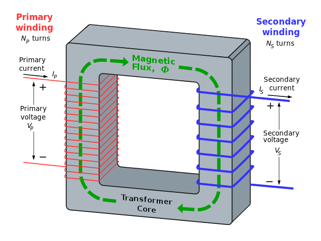
The EMF equation describes the relationship between the induced EMF and the magnetic flux in the transformer. As the magnetic flux linking the windings changes due to the alternating current, it generates a corresponding EMF in the windings. This induced EMF transfers electrical energy from the primary to the transformer‘s secondary Winding.
Factors Influencing the EMF Equation
Several factors influence the EMF equation in transformers. The number of turns in the primary and secondary windings, the magnetic flux density, and the alternating current frequency are key factors that impact the magnitude of the induced EMF. Altering these factors can affect the transformer’s performance characteristics, such as voltage transformation ratio and efficiency.
Design and Analysis of Transformers
The EMF equation is vital in transformer design and analysis. Engineers use it to determine the required number of turns in the windings, select appropriate core materials, and optimize the transformer for specific applications. By considering the EMF equation, designers can ensure that the transformer meets the desired voltage regulation, efficiency, and other performance criteria.
Let,
N1= No. of turns in primary Winding
N2= No. of turns in secondary Winding
Φm = Maximum flux in core in Webers
= Bm x A
F = Frequency of AC input in Hz.
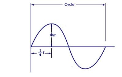
In fig., flux rises from zero to the maximum Φm value in one-quarter of the cycle, i.e., in 1/4 f second.
∴ The average rate of change of flux = Φm /1/4f
= 4 Wb/s or volt
Now, the rate of change of flux per turn means induced e.m.f. in volts.
∴ Average e.m.f./turn = 4 f Φm volts
If flux Φ varies sinusoidally, then r.m.s. The value of induced e.m.f. is obtained by multiplying the average value with the form factor.
Form factor = r.m.s. Value / average value =1.11
∴ r.m.s. value of e.m.f./turn = 1.11 × 4 f Φm
= 4.44 f Φm volt.
Now, r.m.s. value of the induced e.m.f. in the whole of primary Winding
= (induced e.m.f/turn) × No. of primary turns
E1 = 4.44fN1 Φm = 4.44fN1 Bm A —->1
Similarly, r.m.s. Value of the e.m.f. induced in secondary is,
E2 = 4.44fN2 Φm = 4.44fN2 Bm A —->2
From the equation 1 —-> 2 that E1/N1 = E2/N2 = 4.44f Φm.
This means that e.m.f./turn is the same for primary and secondary windings.
In an ideal transformer on no-load, V1=E1 and E2=V2. Where V2 is the terminal voltage
Conclusion
A deep understanding of the EMF equation has driven significant advancements in transformer technology. Engineers have explored innovative designs, such as resonant and multi-winding transformers, improving efficiency, compactness, and versatility. These advancements have enabled the integration of transformers into emerging technologies, including smart grids, renewable energy systems, and electric vehicle charging infrastructure.
FAQs
1. What is the EMF equation of a transformer?
The EMF equation of a transformer is represented by the formula: e = 4.44fnφ, where:
e is the induced electromotive force (EMF) in volts,
f is the supply frequency in hertz (Hz),
n is the number of turns in the coil, and
φ is the magnetic flux in Webers (Wb).
2. How do you calculate the RMS value of induced voltage in a transformer?
To calculate the RMS (Root Mean Square) value of induced voltage in a transformer, you can use the formula Vrms = (e / √2), where e is the induced EMF given by the EMF equation (e = 4.44fnφ).
3. What are the main factors affecting voltage drop in a transformer?
Voltage drop in a transformer is influenced by several factors, including:
Resistance of the transformer coil and its windings
The load current passing through the transformer
Leakage reactance and reactance variation within the transformer
4. What is the significance of the power factor in transformer operation?
The power factor plays a crucial role in transformer operation. It represents the phase difference between the system’s voltage and current. A low power factor can result in higher losses, reduced efficiency, and an increased voltage drop in the transformer.
5. How does the induction motor work based on the principles of electromagnetic induction?
An induction motor operates on the principle of electromagnetic induction. When the stator windings are supplied with an alternating current, a rotating magnetic field is created, which induces a voltage in the rotor windings. This induced voltage causes the rotor to rotate, driving the motor’s mechanical load.
Supporting Article
Basics of Electromagnetic Fields
