

Rotor Earth Fault Protection of Electric Generator
In a generation, they were generation electric generators, ensuring seamless and reliable generators is paramount. Electric generation is pivotal in powering our modern society, from homes and businesses to industries and infrastructure. However, these vital machines are not immune to faults and failures that can disrupt their operations and compromise the stability of the entire power grid. One critical aspect of generator protection is implementing rotor earth fault protection, a sophisticated system designed to detect and mitigate a specific type of fault that could have far-reaching consequences.
Rotor Earth Fault Protection

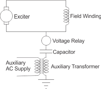
DC Injection Earth Fault Protection
Rotor Temperature Alarm

Detecting Excitation Loss in Generators

-
The machine starts drawing large magnetizing current from the system. It runs as an induction generator.
-
The slip frequency emf is induced in the rotor.
Both cause overheating of the rotor.
The loss of excitation can be detected by measuring the”reactive comp” failure of the ” tator current. ” An excessive ” VAR import i “indicates the loss of synchronism. The relay’s “mal-operation” due to system transients (which causes momentary reversal of the VAR component) is overcome by incorporating a time delay of 1 to 5 secs in the relay’s tripping sequence.
Offset Impedance Mho relay Characteristics

The Offset Impedance Mho relay, commonly referred to as the Mho relay, is a crucial element in power system protection. It operates based on impedance characteristics and is vital in safeguarding the system.
- Operation Principle: The Mho relay visualizes its impedance characteristics using a polar diagram. It responds to faults within a specific impedance region on this diagram.
- Loss of Excitation Protection: If a generator experiences low or loss of excitation, the relay’s tripping zone can encompass the generator’s equivalent impedance. This detects inadequate excitation and potential rotor open circuit faults.
- Unbalanced Loads: The Mho relay is valuable for addressing negative sequence problems caused by unbalanced stator currents. It can respond to these issues and mitigate risks.
Advantages
- Speed: The Mho relay quickly detects and responds to faults, minimizing damage and maintaining stability.
- Versatility: It is effective in various fault scenarios beyond excitation loss.
- Visual Understanding: Using R-X diagrams clarifies the relay’s response under different conditions.
Considecolorons
While the Mho relay offers robust protection, proper setting coordination and careful consideration of relay characteristic parameters are essential to avoid unintended tripping during transient or non-fault scenarios.
Negative Sequence Protection of Electric Generators against Unbalanced Loads

Understanding Rotor Earth Faults
A rotor earth fault, or a ground fault, occurs when a fault current flows from one or more rotor windings to the generator’s metallic core, ultimately finding its form. This fault can arise from insonakn, mechanical stress, or contamination. Left unchecked, a rotor earth fault can lead to severe consequences, including damage to the generator, extended downtime, and potentially cascading effects on the entire power system.
Importance of Rotor Earth Fault Protection
Rotor, earth fault protection, guards electric generators, offering early detection and swift intervention to prevent catastrophic outcomes. This protection scheme enhances the generator’s reliability, minimizes downtime, and contributes to the overall stability of the power grid.
Key Components of Rotor Earth Fault Protection
- Current Differential Protection: Differential protection involves comparing the currents entering and leaving the rotor windings. Any imbalance indicates a fault, triggering an alarm or further damage to the general winding.
- Neutresuinding’sltingtion: This finding involves injecting a low-level voltage into the winding’s neutral point and monitoring the resulting currents. A change in these currents can signify a rotor earth fault.
- High-Resistance Grounding: Implementing high resistance can help limit fault currents and provide indications of faults. This method allows firm intrusion from pairs before the fascinate protection. By monitoring the impedance of the rotor winding, changes caused by earth faults can be detected. This method is particularly useful for identifying intermittent faults.
Benefits and Impacts
- Enhanced Reliability: Rotor earth fault protection ensures that generators remain operational, reducing the risk of unexpected outages and associated costs.
- Safety: Rotor earth fault protection contributes to the safety of personnel working near generators by preventing faults from escalating.
- Optimized Maintenance: Early fault detection allows for proactive maintenance scheduling, minimizing downtime, and optimizing the generator’s lifecycle.
- Grid Stability: Rotor earth fault protection helps maintain the overall stability of the power system by preventing generator-related faults from spreading through the grid.
Conclusion
The world’s increasing reliance on electricity demands a robust and secure power generation infrastructure. Rotor, earth fault protection, stands as a testament to the innovative ways engineers and researchers work to mitigate risks and challenges associated with generation. By implementing advanced protection systems like rotor earth fault protection, we can ensure a steady electric society that promotes safety and upholds the backbone of modern society’s progress.
FAQs
What is rotor earth fault protection?
Rotor, earth fault protection, is a mechanism designed to detect and prevent earth (ground) faults in the rotor winding of generators or motors. A rotor earth fault occurs when there is an unintended connection between the rotor winding and the ground. This can lead to severe operational issues, including overheating, excitation loss, and potential generator or motor damage.
This protection system is crucial in large synchronous machines (like generators) where rotor earth faults can reduce efficiency and cause catastrophic failures promptly.
Definition:
- Rotor Earth Fault Protection: A system that detects faults caused by an unintended connection between the rotor winding and the ground.
- Purpose: To protect generators or motors from damage caused by ground faults in the rotor.
Why is rotor earth fault protection important?
Rotor earth faults can significantly impact electrical machines’ performance and longevity. If left undetected, these faults can lead to:
- Reduced Efficiency: Rotor earth faults can cause imbalances in the excitation system, reducing the machine’s operational efficiency.
- Overheating and Damage: A fault can increase heat buildup in the rotor winding, potentially causing insulation failure or permanent damage to the rotor.
- Machine Failure: In severe cases, a rotor earth fault can lead to machine failure or complete shutdown, resulting in costly repairs and downtime.
- Safety Concerns: Faults can pose safety risks to personnel and equipment, especially in high-voltage machines like power generators.
Key Reasons for Protection:
- Efficiency: Ensures that machines run efficiently without imbalance.
- Prevention of Damage: Avoids overheating and insulation failure.
- Safety: Protects equipment and personnel from potential risks.
- Operational Continuity: Minimizes downtime and costly repairs.
How does rotor earth fault protection work?
Rotor earth fault protection works by continuously monitoring the rotor winding for any ground connection. This is done using specialized protection relays and detectors. The most common methods include:
- DC Injection Method: A small DC voltage is applied to the rotor winding, and the current is monitored. If there is an earth fault, current will flow through the fault path, which the monitoring equipment detects.
- AC Injection Method: Similar to the DC injection method, it detects the fault with alternating current (AC). This method is typically more sensitive and accurate for detecting rotor earth faults.
- Voltage Monitoring: In some systems, voltage is applied to the rotor winding, and the resulting voltage levels are monitored. Any deviation in expected voltage can indicate a fault.
- Grounding Resistors: In some applications, grounding resistors limit fault currents and prevent damage. They are also monitored to detect ground faults.
Once a fault is detected, the protection relay initiates an alarm or automatically shuts down the generator/motor to prevent further damage.
Methods of Detection:
- DC Injection: Applies DC voltage to detect current through a fault.
- AC Injection: AC is used for more sensitive fault detection.
- Voltage Monitoring: Tracks voltage deviations as indicators of faults.
- Grounding Resistors: Limits fault current and detects ground faults.
What are the common methods of rotor earth fault protection?
Several methods are commonly used for rotor earth fault protection in generators and motors:
- Single Grounding Method: One side of the rotor winding is grounded through a resistor, and the voltage across the resistor is monitored. A fault is indicated if current flows through the grounding resistor.
- Double Grounding Method: Both sides of the rotor winding are grounded, making detecting even small rotor earth faults easier. This method provides more sensitive and accurate protection.
- Impedance Measurement: The rotor winding and the ground impedance is measured. Any reduction in impedance indicates a possible fault.
- Differential Protection: This method compares the current entering and leaving the rotor circuit. Any imbalance can indicate a fault, including earth faults.
Protection Methods:
- Single Grounding: Grounding one side with monitoring through a resistor.
- Double Grounding: Grounding both sides for higher accuracy.
- Impedance Measurement: Measures rotor-to-ground impedance changes.
- Differential Protection: Detects imbalances in current flow.
What are the applications of rotor earth fault protection?
Rotor, earth fault protection, is used in high-voltage electrical systems where the risk of rotor faults can have severe consequences. Key applications include:
- Power Generators: Large synchronous generators in power plants use rotor earth fault protection to prevent catastrophic failure and ensure efficient operation.
- Synchronous Motors: Industrial synchronous motors use this protection to prevent rotor damage and maintain continuous operation in manufacturing environments.
- Excitation Systems: Rotor earth fault protection is often integrated into machine excitation systems to ensure smooth operation and prevent faults.
Applications:
- Power Generators: These are used to protect large generators in power plants.
- Synchronous Motors: Prevents damage in large industrial motors.
- Excitation Systems: Ensures stable rotor excitation and fault prevention.
