

Radio Frequency Choke – Function, Types, and Applications
When you encounter issues with high-frequency interference in electronic circuits, a Radio Frequency (RF) choke might be the solution you need. This passive component, typically a coil of insulated wire on a magnetic core, blocks high-frequency signals, allowing direct current (DC) to pass. Understanding the types and materials of RF chokes, like iron powder or ferrite, can substantially impact the circuit’s performance. But is selecting the right RF choke as straightforward as it seems? Let’s explore how these components maintain signal integrity and what factors you should consider.
Key Takeaways
- RF chokes block high-frequency signals while allowing DC currents to pass through.
- They are typically coils of insulated wire on a magnetic core.
- Key materials include iron powder, ferrite cores, and ferrite beads.
- Essential for reducing electromagnetic inteelectromagneticer supplies and signal lines.
- Modern RF chokes can handle DC currents up to 15A and cover bandwidths from 5 MHz to 10 GHz.
What Is an RF Choke?
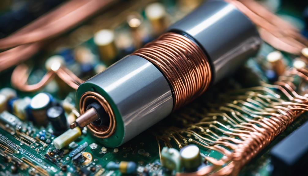
An RF choke is a passive electronic component that blocks high-frequency signals while letting DC signals pass through. It’s a coil of insulated wire wound on a magnetic core. This configuration allows the RF choke to act as an inductor, which is fundamental to its ability to impede high-frequency interference.
Eliminating digital RF noise is vital when dealing with electronic circuits. That’s where RF chokes come in. Integrating an RF choke can effectively prevent electromagnetic and radio frequency interference electromagnetics, which is important for guaranteeing that your devices operate smoothly without unexpected disruptions.
RF chokes are indispensable for protecting DC supply lines. These components ensure that only the desired DC reaches sensitive parts of your electronics, safeguarding them from potential damage caused by high-frequency noise.
Choosing the right RF choke involves several considerations. You must examine the frequency range, impedance, inductance, rated voltage, and current handling capabilities. Each parameter significantly determines how effective the RF choke will be in your specific application. So, understanding these aspects is key to optimizing your circuit’s performance.
Working Principle of RF Chokes
Understanding how RF chokes work involves examining their ability to block high-frequency signals while allowing DC currents to pass unimpeded. You’ll find a coil of insulated wire at the heart of an RF choke. This coil is wound around a magnetic core, vital for its operation. The magnetic core enhances the coil’s inductance, making it more effective at impeding high-frequency signals.
When a high-frequency signal encounters the RF choke, the inductance created by the coil opposes the signal’s rapid changes. Consequently, the high-frequency signal is attenuated or weakened, as it can’t effectively pass through the choke. On the other hand, DC currents, which don’t change rapidly, face minimal opposition from the choke and pass through almost unimpeded.
RF chokes are essential in electronic circuits to eliminate digital RF noise and protect DC supply lines. By blocking high-frequency noise, they help maintain signal integrity and reduce electromagnetic interference and frequency interference (RFI).
This ability to differentiate between frequencies ensures that electronic electromagnetics functions smoothly without succumbing to disruptive noise, making RF chokes indispensable in modern electronics.
Types of RF Chokes
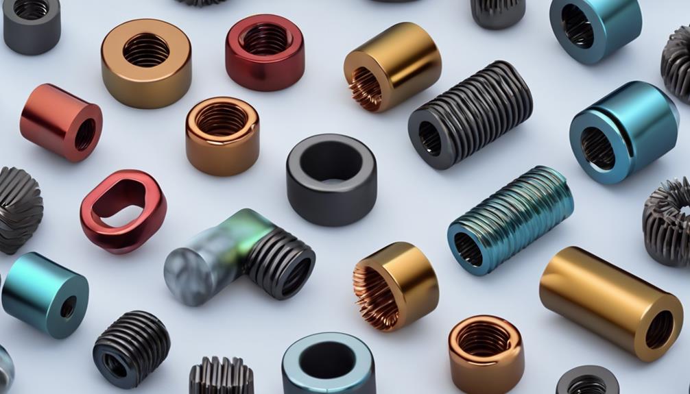
Several RF chokes are designed to meet specific frequency requirements and applications. RF chokes, in particular, are tailored to block radio frequencies while allowing DC or low-frequency AC currents to pass. They commonly use iron powder or ferrite cores to enhance inductance, making them highly effective at filtering unwanted high-frequency signals.
One prevalent type is the ferrite bead choke. These chokes are small and efficient, often wound in complex patterns to maximize their inductive properties. They’re typically employed to block electronic noise in power cords, ensuring the smooth operation of your electronic devices.
Another variety includes chokes designed for higher frequencies. These might employ non-magnetic cores with low inductance, catering to applications where minimizing interference at very high frequencies is essential. The material and winding patterns of these chokes are meticulously chosen to meet the specific needs of high-frequency environments.
Lastly, you’ll come across audio frequency chokes, which, although not RF chokes, provide context. These use ferromagnetic cores to increase inductance and are and are tailored for audio frequencies rather than radio frequencies. Understanding these types helps you select the right RF choke for your needs.
Applications of RF Chokes
RF chokes are essential in power supplies, signal lines, and audio equipment to block high-frequency noise and reduce electromagnetic interference. They are also vital in rectifier power supplies, motor controllers, and switching power supplies to maintain signal integrity. By suppressing unwanted electromagnetic radiation, chokes guarantee your devices operate smoothly without the disruptive effects of radio frequency interference.
In industrial and electrical applications, RF chokes play a significant role in maintaining system performance. They suppress noise in telecommunications equipment, enhancing the overall quality of the transmitted signals. For instance, common mode chokes allow differential currents to pass while blocking interfering signals. This makes them invaluable in various electronic systems where signal quality is paramount.
Conversely, differential mode chokes are designed to suppress noise between lines with a single winding. They contribute to the overall performance of electronic circuits by filtering out unwanted frequencies and ensuring a clean signal path. Incorporating these chokes into your designs effectively mitigates radio frequency interference, leading to more reliable and efficient electronic systems.
Materials Used in RF Chokes
Manufacturers often use materials like iron powder, ferrite cores, and ferrite beads to enhance the performance of RF chokes. These materials are chosen for their unique properties, which greatly improve the efficiency of RF chokes in blocking unwanted radio frequency signals.
Ferrite cores are particularly popular because they offer high magnetic permeability and low eddy current losses. This makes them ideal for use in a wide range of frequencies. The high permeability of ferrite cores allows for a greater inductance in a smaller volume, which is essential for compact electronic designs.
Iron powder cores, on the other hand, are known for their high magnetic permeability and low losses at high frequencies. These cores are especially useful in applications where stable inductance and minimal signal distortion are crucial. Iron powder’s magnetic properties make it an excellent choice for high-frequency inductors used in RF chokes.
Ferrite bead chokes are another effective solution for blocking high-frequency noise, particularly in power cords and cables. They provide a simple yet effective means of reducing electromagnetic radiation. Choice of core material—whether it’s ferrite cores, iron powder, or ferrite beads—plays a pivotal role in determining the performance and efficiency of the RF choke.
How toelectromagnetichoke
When selecting an RF, determine the frequency range you must block first.
Ensure the choke can handle the current required for your application without overheating.
Lastly, choose a choke with the right inductance value to manage high-frequency signals effectively.
Desired Frequency Range
Selecting the right RF choke starts with identifying the specific frequency range you must block. The effectiveness of a radio frequency choke hinges on its ability to filter out unwanted signals while allowing desired ones to pass through. To achieve this, consider the frequency range of the interference you want to eliminate.
An RF choke designed for your specific frequency range will guarantee that unwanted signals are effectively blocked, optimizing your system’s performance.
When choosing an RF choke, you must align its frequency range with the frequencies causing interference. This precision helps in maintaining the integrity of your desired signals. For instance, if your application faces interference at 1 MHz, selecting an RF choke capable of blocking frequencies around that range is essential.
Understanding the exact frequency range you need to target helps you make an informed decision, ensuring the choke is suitable for your application.
Current Handling Capacity
Evaluating an RF choke’s handling capacity is crucial to guarantee it meets your application’s requirements. RF chokes need to handle the DC current flowing through your circuit without overheating or failing. When selecting an RF choke, you must consider its maximum DC current rating. Mini-Circuits, for example, offer RF chokes that can effectively handle up to 15A of DC.
Choosing the right RF choke ensures efficient operation in your RF systems. Here are the key steps to make sure you select an RF choke with the appropriate current handling capacity:
- Determine the maximum DC in your application: Make sure the RF choke’s current handling capacity matches or exceeds this value.
- Check the RF choke’s datasheet. Look for the maximum DC current rating and ensure it matches your needs.
- Consider safety margins: Select an RF choke with a slightly higher current rating than your maximum requirement to account for unexpected increases in current.
- Evaluate thermal performance: Ensure the RF choke can dissipate heat effectively to prevent overheating.
Inductance Value Selection
How do you select the appropriate inductance value for your RF choke to guarantee peak performance in your circuit? First, focus on the desired frequency range for blocking high-frequency signals. The inductance value selection is important because it determines how effectively the RF choke can block unwanted RF signals.
Next, match the inductance value with the impedance requirements of your application. An RF choke with the correct inductance ensures that the circuit operates efficiently without interference. Make sure the RF choke can handle the maximum charge induced, which translates to its ability to block high-frequency signals effectively.
Additionally, consider the rated voltage and current specifications. An RF choke needs to handle the operational conditions of your specific application without failure. Opt for a choke that meets these needs while maintaining impedance for your circuit.
Here’s a quick reference table to help with your inductance value selection:
| Parameter | Consideration | Action Required |
|---|---|---|
| Frequency Range | High-frequency signals | Select the appropriate inductance value |
| Impedance Requirements | Match with application needs | Ensure impedance compatibility |
| Maximum Charge Induced | Effective RF signal blocking | Choose based on maximum charge handling |
| Voltage and Current Ratings | Specific application conditions | Ensure ratings meet operational conditions |
Installation Tips for RF Chokes
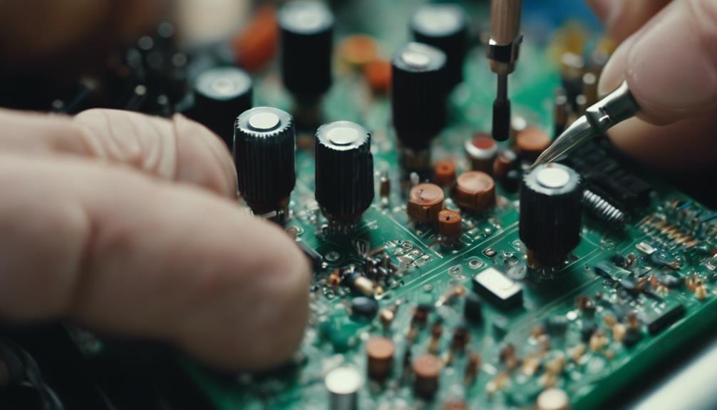
When installing RF chokes, secure them with hot melt glue to prevent any shifts that could alter their electrical characteristics. A secure installation guarantees your Radio Frequency choke maintains its intended performance, avoiding disruptions in your circuits.
Here are some essential tips for a successful installation:
- Avoid Metal Near the Core: Keep screws and other metal objects away from the choke’s core. Metal can interfere with the choke’s magnetic field, affecting its efficiency.
- Prepare the Wire Ends: Scrape off the insulation at the ends of the coil wires before connecting terminals. This guarantees a reliable electrical connection and reduces the risk of poor performance.
- Tin the Wire Ends: Apply a thin layer of solder (tinning) to the ends of the coil wires. This step simplifies the connection process and enhances conductivity, smoothing your installation.
- Secure Connections Properly: Use screw cup terminals at designated points, such as between terminals 3 and 4 on the lower row. Properly securing these connections ensures stability and reduces the likelihood of connectivity issues.
Common Issues With RF Chokes
When dealing with RF chokes, you might encounter impedance-matching problems affecting signal quality.
Heat dissipation is another concern that could lead to thermal issues if not adequately addressed.
Additionally, RF chokes have frequency range limitations that you must consider for best performance.
Impedance Matching Problems
Impedance mismatches in RF chokes often lead to signal reflection and significant power loss, undermining the circuit’s overall performance. When dealing with AC signals, an impedance mismatch can create standing waves, drastically reducing signal integrity. This mismatch means the RF choke’s impedance doesn’t align with the circuit’s characteristic impedance, causing reflected signals and inefficient power transfer.
To guarantee your RF circuits function at their best, avoid these common impedance-matching problems:
- Incorrect Component Selection: Using components with mismatched impedance values can cause significant power losses and signal reflection.
- Inadequate Tuning: Failing to tune your circuit properly can result in an impedance mismatch, which can lead to standing waves and reduced signal quality.
- Improper Layout: The physical layout of your components can affect impedance. Ensure the layout minimizes parasitic elements that could disrupt impedance matching.
- Neglecting Cable Impedance: Using cables with incorrect impedance can introduce mismatches, resulting in signal degradation and power loss.
Heat Dissipation Concerns
Efficient heat dissipation is essential to prevent performance degradation and guarantee the longevity of your RF chokes. When high-frequency signals pass through these components, they can generate excessive heat. If not managed properly, this heat can greatly impact the performance and efficiency of your RF chokes.
One of the main contributors to heat buildup is high current levels, especially during prolonged use. As the temperature rises, the materials and components within the RF chokes can start to degrade. Overheating can lead to changes in impedance, reduced efficiency, and even permanent damage.
To combat these issues, effective thermal management strategies are vital. These could include using heat sinks and thermal pads and ensuring adequate airflow around the RF chokes. Additionally, selecting materials with high thermal conductivity for the RF chokes can help dissipate heat more effectively.
Frequency Range Limitations
As you guarantee proper heat dissipation for RF chokes, it’s equally important to understand their frequency range limitations to maintain effective signal filtering. RF chokes are designed to block high-frequency signals, but their effectiveness can vary depending on their frequency range capabilities. If you don’t consider these limitations, you might face issues like improper blocking of specific frequencies, leading to signal leakage and interference.
Here are four key points to keep in mind regarding frequency range limitations:
- Design and Material Composition: The design and materials used in RF chokes substantially impact their frequency range limitations. Certain materials and designs may be better suited for specific frequency ranges, affecting their ability to filter signals effectively.
- Inadequate Blocking: If an RF choke can’t handle a particular frequency range, it may not block those frequencies adequately, allowing unwanted signals to pass through.
- Effective Signal Filtering: Selecting RF chokes with the appropriate frequency range ensures effective signal filtering and interference suppression, which is crucial for maintaining the integrity of your RF system.
- Application-Specific Selection: Understanding the frequency limitations of RF chokes helps you choose the right components tailored for specific applications, ensuring your RF system performs as intended.
Innovations in RF Choke Technology

With the advancements in RF choke technology, you’re now looking at high-frequency models with impressive bandwidths ranging from 5 MHz to 10 GHz. These innovations are game-changers, especially when managing DC and radio frequencies efficiently.
Modern RF chokes are designed to tackle Electromagnetic IntElectromagneticively, guaranteeing that your devices perform at their best without unwanted signal disruptions.
Mini-Circuits are at the forefront of this technological leap, offering RF chokes as small as 0.15 x 0.15 x 0.15 inches. Despite their tiny size, this chokes Electromagnetic resistance and minimal parasitic capacitance provide superior performance.
If you’re dealing with wideband frequencies, these models are particularly beneficial as they can handle DC currents up to 15A.
Mini-Circuits’ diverse range of RF choke products also means you can find tailored solutions for various RF system requirements. Whether you’re working on advanced communication systems or cutting-edge electronics, these innovations guarantee you have the right components to filter and manage radio frequencies efficiently.
Gone are the days of bulky, inefficient chokes; today’s technology provides more compact, powerful, and reliable solutions.
Conclusion
To wrap it up, RF chokes are crucial for blockIt would be best if you placed high-frequency signals while letting DC signals through. They’re used in various electronic circuits to guarantee clean and efficient performance.
By understanding how they work, the types available, and how to choose and install them, you’ll keep electromagnetic in electromagnetic updated on innovations and always have the best tools for maintaining signal integrity in your projects.
FAQs
Where Do You Put an RF Choke?
You should place an inductor near the antenna connection for effective signal isolation. Proper inductors ensure that unwanted RF noise is blocked, improving the device’s performance and maintaining the integrity of your electronic circuits.
What Is AF Choke and RF Choke?
You’ve asked about AF and RF chokes. Choke types differ by frequency bands: AF chokes manage audio frequencies using iron powder or ferrite inductor materials. RF chokes handle radio frequencies, employing varied inductor materials based on needs.
What Is the Purpose of Radio Frequency Choke in the Circuit Given Below?
You use it in the circuit to minimize noise, guarantee impedance matching, and prevent signal interference. It blocks high-frequency signals, allowing only DC signals to pass, thereby protecting and ensuring the smooth operation of the circuit.
What Is the RF Choke Equivalent To?
An RF choke is equivalent to an inductor that provides signal isolation. It uses inductive reactance to block high-frequency signals while allowing DC to pass, effectively achieving frequency filtering in electronic circuits.
