

Revealing Efficiency: Swinburne’s Test Unveiled for DC Machines
The quest for efficient energy utilization in electrical engineering has been a driving force behind technological advancements. One pivotal tool that stands as a beacon of precision in this endeavor is Swinburne’s Test—an ingenious method that unravels the efficiency mysteries of DC machines. This method clarifies machine performance and propels predictive analysis to new heights.
The Essence of Swinburne’s Test
At its core, Swinburne’s Test revolves around the delicate interplay between no-load operation and the intricacies of losses within a DC machine. Operating a DC generator or motor at no load sets the stage for exploration beyond conventional efficiency assessment. A fascinating measurement and evaluation journey begins as the machine hums to life, devoid of external gear.
Operating in Emptiness
The DC machine, be it a generator or motor, assumes the role of an engine at this juncture. This no-load operation is the canvas on which the efficiency portrait will be painted. As the machine runs without a load, it reveals its intrinsic losses.
Losses in the Limelight
Amid this tranquil operation, the losses inherent to the machine emerge from obscurity. These losses encompass the core’s hysteresis, eddy current losses, and the ever-present friction and windage losses. Swinburne’s Test turns the spotlight onto these usually unseen culprits, showcasing their role in the machine’s overall performance.
Mapping Efficiency
Armed with the knowledge of these losses, engineers can venture beyond the realm of no-load operation to predict Efficiency across a range of load conditions. The Test offers a tantalizing glimpse into the machine’s potential Efficiency under different operational scenarios.
Significance and Applicability
It’s important to note that Swinburne’s Test isn’t a one-size-fits-all solution. This method applies to DC machines that maintain a constant flux throughout varying operational conditions. These machines include DC shunt machines and DC compound machines.
Elevating Efficiency Analysis
Swinburne’s Test has transcended the boundaries of conventional testing methodologies. It gives engineers a potent tool that measures Efficiency and empowers them to foresee machine behavior under different workloads. This predictive ability fosters a deeper understanding of machine dynamics, enabling informed decisions in optimizing energy utilization.
DC Machine Efficiency via No-Load Loss Method

No-Load Brilliance
The No-Load Loss Method revolves around running a DC generator or motor at no load. This special operating condition lays bare the inherent losses within the machine. When the device operates without an external limitation, it allows the measurement of losses that occur without mechanical work.
Understanding Losses
During this no-load operation, the machine experiences losses attributed to different factors. These losses include core losses (hysteresis and eddy current losses) and friction and windage losses. Each of these elements contributes to the overall energy inefficiency of the machine.
Predictive Power
What makes the No-Load Loss Method particularly powerful is its predictive nature. By quantifying losses under no-load conditions, engineers gain insights into the machine’s behavior under various load conditions. This predictive capability enables informed decisions on efficiency optimization.
Applicability and Scope
The No-Load Loss Method is most effective when applied to DC machines that maintain a constant magnetic flux throughout their operational range. This method finds its ideal canvas in appliances like DC shunt and compound machines, where the change remains consistent regardless of varying operating loads.
Advancing Efficiency Analysis
This method transcends the conventional boundaries of efficiency assessment. It illuminates the often-overlooked losses that erode the overall effectiveness of DC machines. With this knowledge, engineers can strategize for improved energy utilization and performance.
Efficiency Redefined
The No-Load Loss Method redefines efficiency assessment by offering a glimpse into the machine’s performance landscape beyond traditional testing scenarios. It highlights the losses that often evade the spotlight, highlighting their significance in the grand efficiency equation.
Determination of Hot Resistance of Windings
Temperature and Resistance
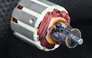
The hot resistance of windings pertains to the resistance of a winding operating under load and at an elevated temperature. Unlike cold resistance, measured at room temperature, hot resistance reflects the resistance when the winding is heated due to current flow and other factors.
Operating under Load
The winding is subjected to a load representing its typical operational conditions to determine the hot resistance. As the current flows through the winding, it generates heat due to the inherent resistance of the winding material.
Measuring the Change
The key aspect of this measurement is tracking the change in resistance as the winding heats up. This is crucial because most materials, including copper used in windings, experience an increase in resistance as temperature rises. The resistance increase is proportional to the temperature rise.
Importance and Applications
The determination of hot resistance holds vital implications in various fields, from power generation to industrial processes. It provides insights into the winding’s performance under operating conditions, enabling engineers to fine-tune designs and optimize energy utilization.
Challenges and Calibration
Accurate measurement of hot resistance can be challenging due to factors like temperature distribution within the winding and the influence of other materials. Specialized measurement techniques and equipment are employed to ensure precise results.
Advancing Efficiency and Reliability
By grasping the behavior of winding resistance under operational conditions, engineers can make informed decisions about system design, load capacity, and component longevity. This knowledge contributes to the overall efficiency and reliability of electrical systems.
A Precision Instrument
Determining the hot resistance of windings serves as a precision instrument in the engineer’s toolkit. It allows for a deeper understanding of how electrical components perform in real-world scenarios, enhancing the precision and effectiveness of design and operation.
Limitations of the Test and Accuracy Challenges
Determination of Constant Losses

To find the Efficiency when running as a motor:
To find the Efficiency when running as a Generator:
Pros and Cons
Pros
-
Since this Test is no load test, the power required is less. Hence the cost is economic.
-
The Efficiency of the machine can be found very easily because the constant losses are well known.
-
This Test is appropriate.
Cons
-
When the DC machine is loaded, this Test does not deliberate the stray load loss that occurs.
-
Using this method, we cannot check the DC machine performances at full load.
Conclusion
As we conclude this exploration, we recognize that electrical engineering is not just about harnessing energy; it’s about understanding it. It’s about deciphering the mysteries of resistance, losses, and performance under various conditions. It’s about harnessing this knowledge to reshape how we design, operate, and manage electrical systems.
