

Sag in Transmission Lines: Causes, Effects, and Solutions
In power transmission systems, sag refers to the vertical drop of a conductor between two support points, such as transmission towers or poles. Though it may seem like a minor mechanical feature, sag plays a vital role in power line safety, efficiency, and reliability. An incorrect sag level can cause ground clearance violations, mechanical failure, line losses, or even catastrophic blackouts.
Sag is influenced by numerous variables, including conductor weight, span length, temperature fluctuations, wind pressure, ice loading, and tension applied during installation. It also varies with terrain, tower elevation, and conductor type. Therefore, the precise calculation and regulation of sag are indispensable parts of power transmission line design.
This article provides an in-depth examination of sag, examining its causes, calculations, and real-world impact, alongside actionable engineering solutions.
What Causes Sag in Transmission Lines?
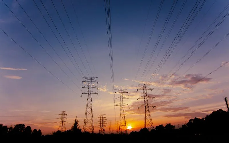
Sag results from a combination of mechanical and environmental factors. Understanding each is key to calculating and managing sag accurately.
Conductor Weight
Heavier conductors, such as ACSR (Aluminum Conductor Steel Reinforced) or bundled conductors, cause higher sag due to their weight. A lightweight alternative, such as AC or ACC, reduces sag but is more costly.
Span Length
The longer the distance between two towers, the greater the sag due to gravitational pull on the unsupported length of the conductor. Shorter spans reduce the cost; however, they increase construction costs
Temperature Changes
Most conductors are metallic and expand when heated. This thermal expansion causes the wire to elongate, lowering tension and increasing sag.
Wind & Ice Loading
In windy conditions, lateral force causes sway, while ice accumulation adds vertical weight. The combination dramatically increases sag and can compromise clearance.
Tension during Installation
Initial tension applied during stringing must be calculated based on the maximum expected temperature and environmental conditions. Under-tensioning leads to excess sag, while over-tensioning can snap wires or damage towers.
Engineering Calculations: How is Sag Determined?
Sag is modeled using either parabolic or catenary curves, depending on the span length and the required accuracy.
Parabolic Approximation (Short Span)
For spans less than 300 meters and small sag-to-span ratios:
Sag (S)=8TwL2
- S = Sag (m)
- w = Conductor weight per unit length (N/m)
- L = Span length (m)
- T = Tension (N)
This simple equation applies to most practical transmission designs.
Catenary Equation (Long Span)
When precision is required for longer spans:
y=a⋅cosh(ax)
Where:
- a is the horizontal tension-to-weight ratio
- cosh(x/a) defines the hyperbolic cosine function
Although complex, software tools are often used to simulate these curves in detail.
Effect of Temperature Variations on Sag Behavior
Temperature fluctuations can significantly impact sag behavior in transmission lines, both throughout the day and across different seasons. As the ambient temperature rises, conductors—typically made of aluminum or other metals expand, resulting in increased sag due to reduced tension. For instance, at 0°C, considered the baseline, there is no thermal expansion, and sag remains at its minimum level. When the temperature rises to 25°C, the conductor expands by approximately 0.1%, leading to a sag increase of about 8%.
At 50°C, the expansion reaches 0.2%, and the sag can grow by nearly 16% compared to the reference. In extreme conditions, such as 75°C, expansion reaches 0.3%, resulting in a sag increase of approximately 25%. These variations underscore the importance of utilizing dynamic line rating systems that incorporate real-time temperature sensors to monitor conductor behavior and ensure sag remains within safe limits under varying environmental conditions.
Wind and Ice: Hidden Dangers in Line Sag
Environmental loads have a significant impact on sag behavior, particularly in cold and storm-prone areas.
Wind Load
It conducts laterally, creating a sway-induced sag. Wind load is calculated as:
F=0.6⋅V2⋅A⋅Cd
- V = Wind velocity (m/s)
- A = Conductor projected area
- C_d = Drag coefficient
Ice Load
Ice adds vertical weight:
- Ice thickness (t): Typically 10–20 mm
- Density: 900 kg/m³
- Weight (w) = Ice volume × density × g
Combined, wind and ice cause multi-directional loading that must be factored into design through NESC or IEC safety standards.
Terrain and Structure Variability: Their Role in Sag
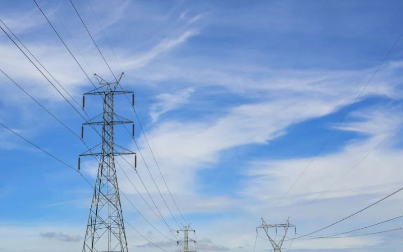
The terrain and structural arrangement of transmission lines play a significant role in determining the amount and behavior of sag. When transmission towers are installed on level ground with equal heights, the resulting sag is typically symmetrical, and the calculation is straightforward using standard parabolic or catenary equations.
However, in cases where there are uneven tower heights, such as when one support is positioned on a hill and the other in a valley, the sag becomes asymmetrical. This requires more complex calculations to ensure that the conductor maintains safe ground clearance throughout the span. Failing to account for these differences can lead to clearance violations and increased mechanical stress.
In inclined or hilly terrain, additional factors must be considered, including the angle of slope, soil stability, and the anchorage strength of support structures. These conditions can significantly affect the conductor profile and tower design. Such terrain-related challenges are frequently addressed in advanced engineering and power distribution applications within the broader field of electronics. To manage these complexities, engineers often rely on advanced simulation software, such as PLS-CADD, which enables precise modeling of terrain features and structural loads.
Understanding the structural behavior of transmission lines under varying terrain is deeply rooted in the principle of electronics that governs electrical and mechanical relationships.
Solutions and Best Practices to Control Sag
To maintain sag within permissible limits, utilities use the following methods:
Use of Composite Conductors
Modern materials like AC, ACCR, and Invar core conductors have:
- High tensile strength
- Low thermal expansion
- Better sag control in high-temperature environments
Reduced Span Length
- More frequent towers reduce sag but increase the cost.
- Often used in urban or forested zones for maximum clearance.
Counterweights and Tensioners
Used especially in railway electrification systems, these devices automatically adjust tension and minimize sag variation due to weather conditions.
Thermal Rating Systems
- Dynamic systems use temperature + tension sensors
- SCADA systems trigger alerts for sag violations in real time
Real-World Examples and Failures Due to Improper Sag
Improper sag has caused several major power failures globally. During the 2003 North American blackout, overheated lines sagged and came into contact with untrimmed trees, triggering a cascading outage that affected over 50 million people in the US and Canada. In Europe during the 2010s, severe ice storms increased conductor weight by over 40%, causing excessive sag, arcing, and power faults.
Similarly, during the 2012 Northern Grid Collapse in India, overloading and high temperatures led to sag-related failures, contributing to a massive outage impacting hundreds of millions. These incidents underscore the importance of accurate sag calculations, real-time monitoring, and regular maintenance to prevent large-scale disruptions.
Monitoring & Inspection Techniques for Sag Management
Manual Methods
- Theodolites and rangefinders for visual measurement
- Conductor templates to check the maximum allowable sag
Digital Tools
- Drones with LiDAR or infrared cameras
- Vibration sensors on conductors
- Smart sensors that record tension, temperature, and strain
Smart technologies ensure proactive rather than reactive maintenance.
Conclusion
Sag in transmission lines is more than just a mechanical outcome. It’s a critical factor in the design, safety, and longevity of power infrastructure. Proper sag management ensures adequate ground clearance, system reliability, and mechanical integrity under all environmental conditions. From conductor type to installation tension, every parameter plays a role. With the help of modern simulations, real-time sensors, and composite conductors, utilities can now tackle sag dynamically and intelligently. The future of reliable power transmission depends not only on electricity but on how we manage the wires that carry it.
FAQs
1. What is sag, and why is it important in power lines?
Sag is the vertical distance between the lowest point of the conductor and the straight line between two towers. It ensures safe clearance from the ground and compensates for thermal expansion and mechanical loading. Incorrect sag can cause power outages or mechanical failure.
2. How is sag affected by temperature?
Higher temperatures cause conductors to expand, lowering their tension and increasing sag. In colder weather, conductors contract, increasing tension and reducing sag. This thermal behavior must be considered in the design.
3. How do engineers calculate sag in uneven terrains?
When tower heights or terrain elevations differ, sag becomes asymmetrical. Engineers use terrain profiles, digital elevation models, and simulation tools like PLS-CADD to calculate accurate sag curves and ensure clearance.
4. What are the maximum allowable sag limits?
Sag limits vary by:
- Voltage class
- Conductor type
- National standards (e.g., NESC, IS, IEC)
- Typical clearance required:
- Low voltage: ~4 meters
- High voltage: ~6–8 meters
- Extra high voltage: 10+ meters
5. Can sag be corrected after installation?
Yes. Utilities can:
- Adjust the conductor tension
- Install vibration dampers or droppers
- Modify tower positioning or height
- Use smart tensioners that respond to thermal changes