

Key Equations for Electromagnetic Induction
When you explore the world of electromagnetic induction, you encounter key equations forming this fascinating field’s backbone. Faraday’s Law proposes the foundation, showing how changes in magnetic flux lead to induced electromotive force. But have you considered how Lenz’s Law determines the direction of the induced current? There’s also the intriguing calculation of EMF in different scenarios, whether across coils or straight conductors. These principles don’t just exist in a vacuum; they have real-world applications that might surprise you. What’s next in this journey through electromagnetic wonders?
Key Takeaways
- Faraday’s Law: Induced EMF (ε) equals -N(dΦ/dt), where N is coil turns and Φ is magnetic flux.
- Magnetic Flux Calculation: Φ equals B · A cos(θ), where B is the magnetic field, A is the area, and θ is the angle.
- Straight Conductor EMF: ε equals B * L * v sin(θ), with B as magnetic field strength, L as length, and v as velocity.
- Lenz’s Law: Induced current direction opposes changes in magnetic flux, maintaining system equilibrium.
- Transformer Equation: The voltage ratio between the primary and secondary coils equals the respective turn ratio, Vp/Vs = Np/Ns.
Faraday’s Law of Induction
When you explore the principles of electromagnetic induction, Faraday’s Law stands out as a cornerstone. It states that an electromotive force (EMF) is induced in a circuit when there’s a change in magnetic flux through it. This relationship is captured by the formula ε = -dΦ/dt, where ε is the induced EMF and Φ represents the magnetic flux.
The negative sign in the equation is essential—it reflects Lenz’s Law, which tells you that the induced EMF will always work to oppose the change in magnetic flux causing it.
Understanding magnetic flux is key. It’s the product of the magnetic field strength (B), the area (A) it penetrates, and the cosine of the angle between the field lines and the area’s normal.
In practical terms, the induced EMF in a coil increases with the number of turns (N), leading to the formula ε = -N(dΦ/dt). This highlights the importance of coil design in electromagnetic induction, especially in applications like electrical generators.
These devices rely on Faraday’s Law to convert mechanical energy into electrical energy, showcasing the Law’s fundamental role in powering modern technology.
Lenz’s Law and Current Direction
Faraday’s Law introduces the concept of induced EMF, but Lenz’s Law explains the direction of the induced current. According to Lenz’s Law, the induced current flows in a way that creates a magnetic field opposing the change in magnetic flux. This principle guarantees the conservation of energy, a fundamental concept in physics.
When the magnetic field through a loop increases, the induced current flows in a direction that generates a magnetic field opposing this increase. Conversely, if the magnetic field decreases, the induced current attempts to maintain the original magnetic field strength.
To determine the direction of the current, you can use the right-hand rule. Point your thumb in the direction of the magnetic field, and your curled fingers will indicate the direction of the induced current. This intuitive tool helps visualize how Lenz’s Law operates in practice.
The negative sign in Faraday’s Law equation, ε = -dΦ/dt, emphasizes this opposition to changes in magnetic flux. Understanding Lenz’s Law is vital for grasping how electromagnetic systems function, highlighting the elegant balance between induced current and the magnetic fields they interact with.
Calculating Induced EMF
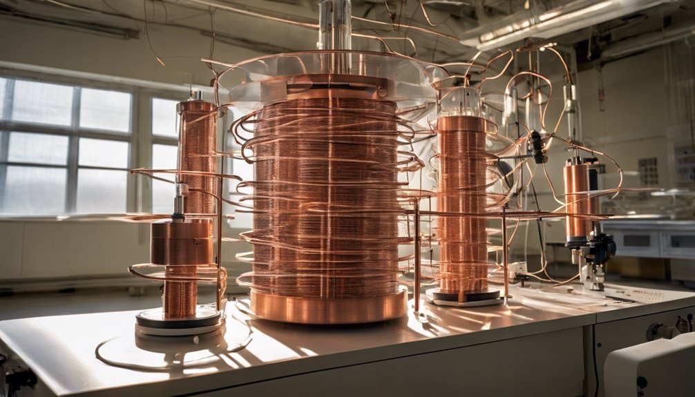
Understanding how to calculate induced electromotive force (emf) is essential for anyone studying electromagnetic induction. You start with Faraday’s Law, which states that the induced emf in a coil equals the negative rate of change of magnetic flux multiplied by the number of turns, expressed as ε = -N(dΦ/dt). Here, N represents the number of turns in the coil, and dΦ/dt denotes the rate of change of magnetic flux.
To find the magnetic flux (Φ), you use the equation Φ = B · A cos(θ), where B is the magnetic field strength, A is the area, and θ is the angle between the magnetic field lines and the normal to the surface area.
Lenz’s Law plays a significant role by indicating that the induced current flows in a direction that opposes the change in magnetic flux, hence the negative sign in Faraday’s equation. When the number of turns increases, the induced emf also increases, allowing you to generate a higher voltage for the same change in magnetic flux.
In cases with a straight conductor moving through a magnetic field, apply ε = B * L * v sin(θ) to find the induced emf, accounting for the conductor’s length, velocity, and the angle with the magnetic field.
Applications of Electromagnetic Induction
Electromagnetic induction finds numerous applications in modern technology, shaping many aspects of daily life. You see its impact every time you use electricity, as electric generators employ electromagnetic induction to convert mechanical energy into electrical energy. By moving a magnetic field past wire coils, they induce an electromotive force (EMF), effectively powering our world.
Transformers also utilize electromagnetic induction to adjust voltage levels in AC systems. They either step up or down voltage, ensuring efficient power distribution across vast distances. This application of induction is essential for delivering electricity to homes and industries.
Induction cooktops revolutionize cooking in the kitchen by generating heat directly in cookware. They induce currents in ferromagnetic materials, leading to rapid and efficient heating. This not only saves time but also conserves energy.
In the medical field, magnetic resonance imaging (MRI) machines rely on electromagnetic induction principles. They generate images of the body’s internal structures by inducing electromagnetic fields and analyzing the response of atomic nuclei.
Additionally, eddy currents are harnessed in eddy current brakes, which use induced currents to create opposing magnetic fields, effectively slowing down or stopping objects like trains.
These diverse applications highlight the transformative power of electromagnetic induction in everyday life.
Managing Eddy Currents

Managing eddy currents is essential for optimizing the efficiency of electrical devices. When changing magnetic fields induce currents in conductors, these eddy currents can cause energy loss due to electrical resistance, often manifesting as heat. This is particularly problematic in devices like transformers and AC motors, where high frequencies exacerbate heating and reduce efficiency.
To combat this, transformers can be constructed using laminated metal sheets. These sheets are insulated from one another, disrupting the path of induced currents and minimizing energy loss.
Consider using materials with high electrical resistance, such as ferrite or iron powder cores, in high-frequency applications. These materials limit the flow of eddy currents, reducing unnecessary heat production.
Additionally, eddy current brakes offer a clever solution for managing these currents. By utilizing the magnetic fields created by the induced currents, these brakes provide a non-contact method of slowing down objects. They oppose motion without physical friction, adding a layer of efficiency and wear reduction.
Conclusion
In understanding electromagnetic induction, you’ve explored key equations like Faraday’s Law, which connects the change in magnetic flux to induced EMF. You’ve seen how Lenz’s Law helps you determine the current direction, ensuring you grasp the fundamental principles. Calculating induced EMF in coils and straight conductors enables you to apply these concepts practically. Remember, managing eddy currents is essential for efficiency. Embrace these insights, and you’ll master the applications of electromagnetic induction confidently.
FAQs
1. What Are the Formulas of Electromagnetic Induction?
You’ll use Faraday’s and Lenz’s Law to calculate electromotive force. Consider magnetic flux changes and induced current direction. Coil turns to affect results in transformers, related voltages, and turns, such as induction heating and magnetic fields, aid energy conversion.
2. What Are the Formulas of Induced Emf?
When calculating induced voltage, use Faraday’s Law: ε LawdΦ/dt. Consider Lenz’s law for Lawrection in circuit analysis, magnetic flux changes, coil turns, and time rate—factor in inductive reactance for alternating current energy conversion.
3. What Are the Equations for Induction?
You’re exploring induction equations, focusing on Faraday’s and Lenz’s Laws. Understand magnetic flux, induced current, and electromagnetic waves. Immerse yourself in self and mutual induction, explore applications like heating, and grasp transformer principles for practical insights.
4. What Are the Basic Electromagnetism Formulas?
Basic electromagnetism formulas include Faraday’s Law and Lenz’s La: magnetic flux, electromotive force, and induced current play essential roles in considering the magnetic field, coil turns, energy transfer, AC circuits, and transformer efficiency for a thorough understanding.
