

Principle of Power System | Basics, Components & Operation
Phases of Electric Power System
In general, delineating an electric-powered power scheme includes some steps. Foremost, Power Plants as a source of Power. Then, high-voltage transmission lines are utilized to move Power from one place to another (i.e., power plants to power substations). Power substations with their step-down transformers are established for reducing the voltage to apt levels to be circulated. As a last stage, circulation schemes are used to give the customer his need for electrical energy. All these stages are shown in the figure below.
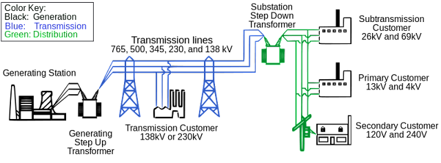
Here is a brief description of each phase:
Generation
The generation phase is where electrical energy is produced in power plants. Various types of power plants, such as thermal power plants, and viable energy sources like solar and wind farms convert different forms of energy into electricity. The generated electricity is usually in the form of alternating current (AC) at high voltages.
Transmission
After generating electricity, it must be transmitted over long distances from power plants to load centers or substations. This is achieved through a network of high-voltage transmission lines. The transmission phase aims to transport electricity while minimizing power losses efficiently. High voltages reduce the current, enabling the transmission of large amounts of Power over long distances.
Distribution
Once the electricity reaches the substations, the distribution phase begins. Substations are crucial in reducing the voltage from transmission levels to appropriate levels for distribution to end-users. Before electricity is distributed through a network of distribution lines. The distribution phase ensures that electricity is delivered to homes, businesses, and industries reliably and safely.
Utilization
The utilization phase is the final stage of the electric power system. At this stage, electrical energy is consumed by end-users to power various devices and systems, including residential, commercial, and industrial applications. Customers receive electricity through their electrical infrastructure, such as electrical panels and wiring, which connect to the distribution lines. The electricity is then used for lighting, heating, cooling, operating machinery, and other electrical loads.
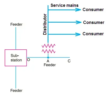
It is important to note that these phases are interconnected and rely on each other to ensure a reliable electrical energy supply. Any disruption or failure in one step can affect the entire power system. Therefore, the design, operation, and maintenance of each step are crucial for maintaining the overall stability and efficiency of the electric power system.
Working Principle of Transformer
The working principle of a transformer lies in the fundamental principles of electromagnetism. A transformer is a static electrical device that transfers electrical energy between two or more circuits through electromagnetic induction. It is vital in electrical power systems, facilitating voltage transformation, isolation, and power distribution.
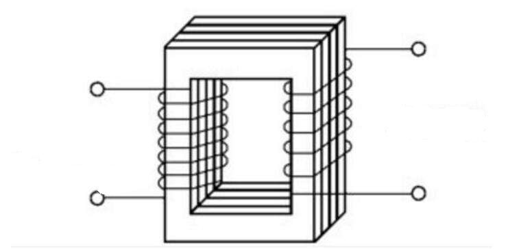
Here is a breakdown of the working principle of a transformer:
Construction
A transformer consists of two essential components: a primary winding and a secondary winding. These windings are typically coils of insulated wire wrapped around a magnetic core made of laminated iron or steel. The primary winding receives the input voltage, while the secondary winding delivers the output voltage.
Faraday’s Law of Electromagnetic Induction
The working principle of a transformer is based on Faraday’s law of electromagnetic induction. According to this law, when the current flowing through a conductor changes, it induces a voltage in an adjacent conductor or coil. In a transformer, the primary winding is connected to an alternating current (AC) power source, creating a varying magnetic field around the primary coil.

Voltage Transformation
The primary and secondary windings have a different number of turns, allowing the transformer to step up or down the input voltage. A transformer that increases the voltage from the primary to the secondary winding is called a step-up transformer. Conversely, a transformer that decreases the voltage from the primary to the secondary winding is known as a step-down transformer.
Power Transfer
The power transfer between a transformer’s primary and secondary windings depends on the turn ratio and the impedance of the windings. As per the principle of energy conservation, the Power on the primary side is equal to the emphasis on the secondary side, neglecting losses. Thus, a transformer enables efficient electrical power transfer from the primary circuit to the secondary course.
Efficiency and Losses
While transformers are highly efficient, they are not perfect, and there are losses associated with their operation. The major losses in a transformer include copper losses (due to resistance in the windings), iron losses (caused by magnetic hysteresis and eddy currents in the core), and stray losses (leakage flux and losses in insulation). Efforts are made to minimize these losses and improve the efficiency of the transformer.
Working Principle Of Generator
The working principle of a generator is based on Faraday’s law of electromagnetic induction, similar to that of a transformer. A generator is a device that converts mechanical energy into electrical energy through the rotation of a conductor within a magnetic field. It is a fundamental component in power plants and various applications requiring electricity generation.

Here is an overview of the working principle of a generator:
Magnetic Field
A generator has two essential components: a magnetic field and a conductor. The magnetic field is typically created by either permanent magnets or electromagnets. It establishes a magnetic field in the region where the conductor will rotate.
Conductor and Coils
The conductor, often in the form of a coil or wire, is placed within the magnetic field. The conductor is usually made of copper or aluminum due to their excellent electrical conductivity. The ring may be wound on an armature, a rotating component within the generator.
Rotation
The conductor or coil is rotated within the magnetic field to generate electricity. This can be achieved by various means, such as using a turbine powered by water, steam, or gas or rotating a shaft by an engine or other mechanical source. The process causes the conductor to cut across the magnetic field lines.
Electromagnetic Induction
According to Faraday’s law of electromagnetic induction, when a conductor cuts across magnetic field lines, an electromotive force (EMF) or voltage is induced in the conductor. The magnitude of the induced voltage is proportional to the rate at which the conductor cuts the magnetic field lines.
Alternating Current Generation
The induced voltage in the conductor is initially alternating. As the conductor rotates, the polarity of the induced voltage changes, resulting in an alternating current (AC). This AC voltage produced by the generator typically has a sinusoidal waveform.
Efficiency and Losses
Generators are not perfectly efficient, and various losses are associated with their operation. These losses include resistive losses in the conductor, core losses due to magnetic hysteresis and eddy currents, and friction losses. Efficient design and operation of the generator aim to minimize these losses and improve overall efficiency.
Conclusion
By adhering to the principle of power systems, stakeholders in the electricity industry can design, operate, and manage power systems effectively. This ensures the reliable, safe, and efficient supply of electrical energy, meeting the evolving demands of consumers while considering environmental sustainability. The principles of power systems continue to evolve as technology advances and new challenges arise, driving the continuous improvement of power system infrastructure and practices.
