

Transformer Winding: Types, Functions, and Maintenance Guide
When you think about transformer winding, you look at the heart of a transformer’s functionality. This component determines how effectively the transformer can handle voltage transformations and current loads. By exploring the various types of windings—such as spiral, disc, and foil—you’ll start to see how each caters to different electrical needs. The choice of materials, like enameled copper wire and specific insulation layers, further impacts performance and reliability. But what happens when you consider the turns ratio, energy losses, and cooling techniques? Understanding these aspects can dramatically influence the efficiency and lifespan of a transformer.
Key Takeaways
- Transformer windings are made from materials like enameled copper wire for high conductivity and insulation.
- Primary and secondary windings determine power handling capacity and adjust voltage or current levels.
- The turn ratio between windings defines whether the transformer is step-up or step-down.
- Different winding types (helical, disc, foil, cylindrical) meet specific voltage and current demands.
- Effective cooling techniques like oil-immersed cooling prevent overheating and maintain transformer performance.
Types of Transformer Windings

Several types of transformer windings are designed to meet specific voltage and current requirements. Understanding these types can help you choose the right winding for your transformer.
Let’s start with helical windings, also known as spiral windings. These are commonly used in high-voltage transformers (110 kV and above) to enhance surge behavior. They’re also used in low-voltage, high-capacity transformers to handle higher currents effectively.
Next, disc windings are similar to helical windings but are typically found in transformers above 25 kV. Their mechanical robustness makes them suitable for applications where durability is key.
Foil windings are designed for high-capacity transformers, making them ideal for situations requiring high currents. Due to their unique design, they offer excellent performance in high-current applications.
Cylindrical windings, which use circular conductors, are often used in low-voltage transformers up to 6.6 kV. Their design allows for better cooling efficiency, making them a good choice for low-voltage needs.
Each winding type—helical, disc, foil, and cylindrical—is essential in ensuring that transformers operate efficiently and reliably and meet various voltage and current demands.
Winding Materials and Construction
Selecting the appropriate materials and construction methods for transformer windings guarantees peak performance and longevity. Because of its high conductivity and excellent insulation, transformer windings typically use enameled copper wire. To prevent short circuits and ensure safety, insulating materials like paper, Mylar, or Nomex are found between winding layers.
Winding construction often involves assembling the coils on bobbins or spools. This technique maintains the coils’ shape and arrangement, improving the transformer’s efficiency and performance. Additionally, impregnation varnish is applied to the windings. This varnish serves multiple purposes: it provides extra insulation, offers mechanical protection, and enhances thermal conductivity.
The materials and methods you use in winding construction directly impact the transformer’s efficiency, performance, and reliability. Enameled copper wire ensures optimal electrical conductivity while insulating materials safeguard against potential electrical faults. Using bobbins keeps the windings well-organized and stable, and impregnation varnish adds a layer of durability and heat management.
Primary and Secondary Windings
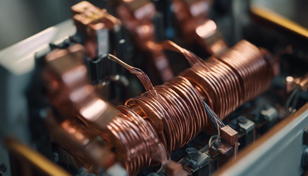
Primary and secondary windings in a transformer play distinct yet interdependent roles in managing and transferring electrical energy. The primary winding draws energy from the power source and is vital for the transformer’s power handling capacity. This winding is designed to create a magnetic flux in the core, which then induces a current in the secondary winding.
Conversely, the secondary winding transmits this energy to the load, adjusting voltage or current levels as needed. Both windings are electrically isolated, indispensable for safety and preventing electrical breakdown. The number of turns in each winding determines the transformer’s output characteristics, which are tailored to meet specific requirements.
Winding design and configuration affect the transformer’s efficiency and performance. Proper insulation between primary and secondary windings ensures safe operation and longevity.
Here’s a simple table to visualize the relationship between the windings:
| Winding Type | Function | Key Characteristics |
|---|---|---|
| Primary | Draws energy from a source | Power handling turns |
| Secondary | Transmits energy to load | Voltage/current adjustment |
| Both | Electrically isolated | Essential for safety |
| Core Interaction | Creates magnetic flux | Induces current |
Understanding these roles helps you appreciate the intricate balance in transformers, ensuring efficient power transfer and operational safety.
Turns Ratio and Voltage
Understanding the primary and secondary windings lays the groundwork for grasping the significance of the turns ratio and its impact on voltage transformation in a transformer.
The turns ratio is the relationship between the number of turns in the primary and secondary winding. This ratio directly influences the voltage levels between these windings through the principle of electromagnetic induction.
When the turns ratio is high, you have a step-up transformer, which increases the output voltage compared to the input voltage. Conversely, a lower turns ratio results in a step-down transformer, reducing the output voltage relative to the input voltage.
Accurately calculating the turns ratio is essential for designing transformers that meet specific voltage requirements and efficiency standards.
For example, if the primary winding has 100 turns and the secondary winding has 200 turns, the turns ratio is 1:2, meaning the voltage is doubled in a step-up configuration. On the other hand, if the secondary winding only has 50 turns, the turns ratio of 2:1 would indicate a step-down transformer, halving the voltage.
Energy Losses in Windings
Energy losses in transformer windings mainly stem from resistive and eddy current losses, which impact the transformer’s efficiency. When current flows through the windings, resistive losses, also known as copper losses or I²R losses, occur. These losses are proportional to the current’s square and the windings’ resistance. Essentially, the higher the current and resistance, the greater the energy losses.
In addition to resistive losses, eddy current losses contribute to energy losses in transformer windings. These losses arise from induced currents circulating within the windings’ conductive material, reducing the transformer’s efficiency. Minimizing energy losses is critical to achieving peak performance.
Reducing these losses improves efficiency and helps reduce heat generation during the transformer’s operation. Excessive heat can lead to premature wear and potential failure, so addressing these energy losses is necessary. By minimizing energy losses in the transformer windings, you ensure better performance and longevity of your transformer.
Improving efficiency is essential for maintaining a transformer’s reliability and cost-effectiveness, making it an important aspect of transformer design and maintenance.
Cooling Techniques
Several effective techniques for cooling transformer windings are available to prevent overheating and maintain peak performance. The most common are natural cooling, forced air cooling, and oil-immersed cooling.
Natural cooling relies on the surrounding air to achieve heat dissipation. This method is important but may not always provide the required cooling efficiency for high-power transformers.
Forced air cooling uses fans to enhance cooling efficiency. By actively circulating air around the transformer winding, this technique greatly improves heat dissipation compared to natural cooling. It’s particularly useful when dealing with higher operating temperatures.
Oil-immersed cooling is another widely used method where transformer windings are immersed in insulating oil. This oil acts as an excellent heat conductor and provides superior heat dissipation. For even greater efficiency, cooling fins or radiators can be added to increase the surface area, further improving the cooling process.
Maintaining ideal operating temperatures is essential for the longevity and performance of transformer windings. Choosing the right cooling techniques ensures your transformer operates efficiently and stays within safe temperature limits, preventing potential overheating issues.
Applications of Transformer Windings

Transformer windings play an important role in determining the efficiency and application of different transformers. In power transformers, the primary winding receives electrical energy, creating a magnetic flux in the transformer core. This flux induces an alternating magnetic field, which transfers energy to the secondary winding, converting it into the desired secondary voltage.
For high-voltage applications (110 kV and above), multi-layer helical windings improve surge behavior and manage high voltages efficiently. These windings help maintain the transformer’s performance under varying electrical conditions.
In contrast, low-voltage, high-capacity transformers often use helical or spiral windings, which handle higher currents more effectively.
Disc windings are typically found in transformers above 25 kV, offering mechanical robustness and stability similar to helical windings. On the other hand, foil windings are designed for high-capacity transformers, making them ideal for scenarios demanding high current requirements.
Cylindrical windings featuring circular conductors are common in low-voltage transformers up to 6.6 kV, providing better cooling and efficiency.
Each winding type addresses specific needs, balancing factors like winding resistance and thermal performance to promote optimal transformer operation. Understanding these applications can help you better appreciate the critical role of transformer windings in electrical energy distribution.
Conclusion
You’ve explored various types, materials, and construction methods to understand transformer windings. You’ve grasped the importance of primary and secondary windings, turns ratio, and the role of energy losses.
With insights into cooling techniques, you can optimize transformer efficiency and longevity. Safe operation hinges on proper insulation and design, ensuring reliable electrical output.
Remember these principles; you’ll excel in creating effective, robust transformers.
FAQs
What are transformer windings?
Transformer windings are coils of wire wound around the core of a transformer. These windings transfer electrical energy from one circuit to another through electromagnetic induction. Transformers typically have two main windings:
- Primary Winding: Connected to the input voltage source.
- Secondary Winding: Connected to the output, the transformed voltage is delivered.
What are the different types of transformer windings?
Transformer windings can vary based on their configuration and application. The common types include:
- Concentric Winding involves winding the primary and secondary coils concentrically, one over the other. This is common in distribution transformers and helps reduce leakage reactance.
- Sandwich Winding: The primary and secondary windings are interleaved in sections to minimize leakage reactance and improve voltage regulation. It’s often used in transformers requiring better voltage control.
- Helical Winding: Consists of helical turns and is typically used in low-voltage, high-current transformers. It provides good mechanical strength and better short-circuit performance.
- Disc Winding: Used in high-voltage transformers, this winding consists of discs connected in series, providing better voltage distribution and insulation.
- Layer Winding: In this type, the winding is done in layers, with insulation between each layer. It’s used in small transformers or where high insulation levels are needed.
What is the role of primary and secondary windings in a transformer?
The primary and secondary windings serve distinct functions in a transformer:
- Primary Winding: This winding is connected to the input power source. When an AC voltage is applied to the primary winding, a magnetic field is created in the transformer core.
- Secondary Winding: The magnetic field generated by the primary winding induces a voltage in the secondary winding. This induced voltage can be higher or lower than the input voltage, depending on the transformer’s design (step-up or step-down).
How does the number of turns in the windings affect a transformer?
The number of turns in the primary and secondary windings determines the voltage transformation ratio of the transformer:
- Turns Ratio: The voltage ratio between the primary and secondary windings is proportional to the turn ratio. Voltage Ratio=Number of Turns in Secondary WindingNumber of Turns in Primary Windingtext{Voltage Ratio} = frac{text{Number of Turns in Secondary Winding}}{text{Number of Turns in Primary Winding}}
- Step-Up Transformer: If the secondary winding has more turns than the primary, the transformer increases the voltage.
- Step-Down Transformer: If the secondary winding has fewer turns than the primary, the transformer decreases the voltage.
What materials are used for transformer windings?
Transformer windings are typically made of copper or aluminum:
- Copper Windings: Copper is preferred for its high electrical conductivity, allowing for efficient energy transfer with minimal losses. Copper windings are also durable and have a long lifespan.
- Aluminum Windings: Aluminum is lighter and less expensive than copper, making it a cost-effective alternative. However, it has lower conductivity, requiring larger cross-sectional areas for the same performance as copper windings.
What is leakage reactance in transformer windings, and how can it be minimized?
Leakage reactance results from magnetic flux that does not fully link the primary and secondary windings, leading to energy losses and voltage drops. It can be minimized by:
- Close Coupling: Placing the primary and secondary windings close to enhance magnetic coupling.
- Winding Configuration: Using configurations like sandwich or concentric windings reduces the distance between the windings and improves magnetic linkage.
- Core Design: Optimizing the core design to reduce the path of leakage flux.
How do transformer windings affect efficiency?
Transformer windings directly impact the efficiency of a transformer:
- Copper Losses: Resistance in the windings causes copper losses (I²R losses), which reduce efficiency. Using low-resistance materials like copper and optimizing winding design can minimize these losses.
- Winding Resistance: Lower resistance in the windings results in less energy lost as heat, improving overall efficiency.
- Proper Insulation: Adequate insulation between winding layers prevents short circuits and maintains efficiency.
What are the challenges associated with transformer windings?
Challenges with transformer windings include:
- Insulation Breakdown: High voltage can cause insulation failure between winding layers, leading to short circuits and transformer damage.
- Mechanical Stresses: During short circuits or sudden load changes, mechanical stresses can deform windings, affecting transformer performance.
- Overheating: Excessive current can cause windings to overheat, leading to insulation breakdown and reduced transformer life.
- Winding Impedance: High impedance in the windings can lead to voltage drops and reduced efficiency.
How is transformer winding insulation achieved?
Transformer winding insulation is achieved through various methods:
- Paper Insulation: Special insulating paper is wound between layers of windings to prevent electrical contact and short circuits.
- Varnish: Windings are often coated with varnish to enhance insulation and protect against moisture and environmental factors.
- Enamel Coating: Individual wires used in the winding may be coated with enamel for added insulation.
- Oil-Immersed Insulation: In oil-filled transformers, the windings are submerged in insulating oil, which provides electrical insulation and helps dissipate heat.
By understanding the role and intricacies of transformer windings, you can better appreciate how transformers function and the importance of proper design and materials in ensuring efficient and reliable operation.
